

On December 15th, 2014, Mirai, the world's first mass-produced fuel cell vehicle (FCV), was unveiled. After more than twenty years of gestation, Toyota’s plan began to emerge. From then on, the fuel cell industry has been surging. Honda, Hyundai, Mercedes and other industrial giants are looking ahead to the future of the fuel cell industry, which is full of unknowns and opportunities. In the past five years, from upstream to downstream, all the fuel cell enterprises were seeking for the potential interests in this fresh unexplored region. Admittedly the advancement of commercialization for FCVs promises the vitality of this industry, but there’re still a lot of technical obstacles lying ahead. What characteristics should the next generation of fuel cell stack possess? What researches should be carried out to improve the cell performance? To answer these questions, we must stay away from various voices, then devote to the investigation of the foothold for FCVs.
The fuel cell power system of Toyota Mirai has shown quite a lot of highlights in different aspects, but it is not our purpose to involve all of them and present a macro discussion. In contrast, details are exactly what we always concern. Thus, from the investigation of flow field structure, we hope to provide some insightful suggestions on the future designs of high-performance fuel cell power system.
Toyota 3-D fine mesh flow field is also called “inverted-scale flow field”, which originates from the schematic diagram officially provided by Toyota (Fig. 1). However, the diagram does not provide a clear description of the detailed structure and mass transfer mechanism. To make it clarified, we carried out optimal visualization on the 3-D flow field and obtained the detailed morphology and geometric parameters of single baffle. Then, we precisely reconstruct the 3-D flow field structure in SolidWorks and discretized the fluid region using an open-source computational fluid dynamic (CFD) software OpenFOAM. In the numerical 3-D flow field model, VOF method is used to capture the phase-interface of the two-phase flow (Fig. 2). To guarantee the accuracy of the model, we firstly conducted independence tests of grid number and flow field size. Then the droplet behaviors, i.e. detachment, deformation and movement, on GDL surface were also validated. After these procedures, we though that the model is reasonable and applicable for the two-phase flow simulation and mass transfer analysis.
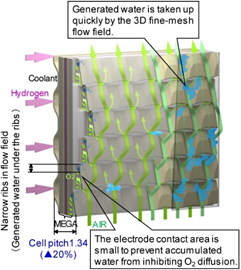
Fig. 1. 3-D fine mesh flow field.
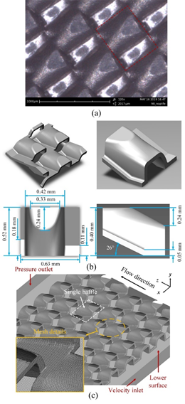
Fig. 2. Morphology reconstruction of 3-D fine mesh flow field: (a) optical microscope image of baffle structure, (b) geometric sizes of a single baffle, (c) computational domain and mesh details.
Single-phase flow characteristics
One of the main functions of flow field is gas distribution. In cathode flow field, the distribution and transportation of oxygen directly influence the oxygen reduction reaction (ORR) at catalyst layer (CL), thus affect the current and power density of PEM fuel cells. There are two criteria generally used to evaluate the mass transfer performance of a flow field. The first one is gas distribution uniformity. Since the active area of catalyst layer is considered distributed uniformly, the uniformity of gas reactant becomes the crucial factor for catalyst utilization. If gas shortage happens in a certain area of CL, both cell performance and durability will be influenced by the degradation of catalyst material (e.g. carbon-supported platinum). The second criterion is convection. In conventional flow channels, gas reactant is mainly transported from flow field to membrane electrode assembly (MEA) through diffusion. But with the increase of current density, this less-effective mass transfer mode cannot meet the requirement of reactant supply and utilization. To solve this problem, worldwide researches have proposed many designs to enhance the convective flow along through-plane direction, such as inserting micro-baffles into flow field and porous material flow field. Based on these two criteria, we evaluated the mass transfer characteristics of 3-D fine mesh flow field.
As shown in Fig. 3, the flow field is divided into three regions with contour and streamlines to analyze the single-phase flow pattern. Several representative flow characteristics are observed and one of them is “gas guidance”. It means when the gas passes through the baffles, a part of it will be guided to below-baffle region and flow pointing to the interface between GDL and flow field (GDL/FF interface). This phenomenon is exactly an effective method to promote convection. Another characteristic is “gas redistribution”. Due to the hindering effect of staggered baffles, gas reactant needs to flow round the baffle structure for the continuous transportation. Therefore, each baffle in the flow field plays a role in the gas redistribution and thus the in-plane uniformity of gas flow is largely promoted. To quantitively measure the effect of above characteristics, the vertical convection and pressure distribution along z-axis (main flow direction) are calculated, as shown in Fig. 4. Compared with parallel channel, the convection in 3-D flow field is largely increased, but the pressure drop is also raised due to the hindrance of baffles. It indicates that the PEM fuel cell efficiency and air compressor configuration will be influenced by the increment pumping loss at high current density condition.
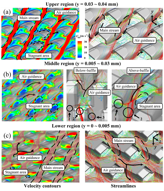
Fig. 3. Single-phase flow pattern (velocity contours and streamlines) of: (a) upper region, (b) middle region and (c) lower region of 3-D fine mesh flow field.
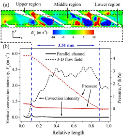
Fig. 4. (a) Contour of y-component of velocity at x=0 mm plane of 3-D fine mesh flow field, (b) vertical convection velocity and pressure distributions along z-axis.
In addition, we also calculated the oxygen utilization rate of the two flow fields. It is found that the utilization rate of 3-D flow field is 1.35 times of parallel channel. This is due to not only the enhanced convection, but also the reduced GDL/FF interface area, i.e. enlarged gas passage area.
Two-phase flow characteristics
At the three-phase interface in catalyst layer, the oxygen adsorbed on the Platinum surface gains electrons and reacts with hydrogen irons. Then, most of the produced water needs to be repelled from the PEM fuel cell through GDL (MPL) and flow field except for the part used to humidify PEM. At present, the operating temperature of PEM fuel cell is around 80℃, which means that the main part of water is removed in liquid form. In this case, the gas transport is significantly influenced by the liquid behaviors, and the analysis of mass transfer in GDL or flow field is thus a two-phase flow problem.
Table 1 and Fig. 5 exhibit the configurations and liquid behaviors of two-phase flow cases, respectively. In this study, the effects of inlet air velocity, liquid droplet size and baffle wettability on mass transfer characteristics are discussed. Five observed typical droplet behaviors are used to explain the simulation results in the following discussion.
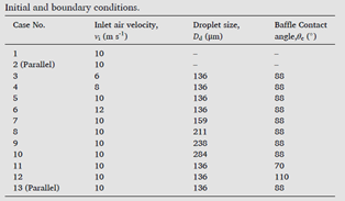
Table. Initial and boundary conditions of the cases.
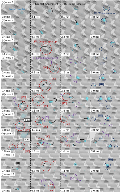
Fig. 5. Typical liquid behaviors of cases 3-12.
1. Droplet development and detachment. This droplet behavior is a selection basis of the initial and boundary condition. In conventional flow channels, when liquid water is expelled from GDL to flow field, the droplet detachment size is related with both the characteristic size of channel and inlet air velocity. According to previous literatures and the geometric feature of 3-D flow field, we confirmed the concerned sizes of droplets expelled from the lower surface of flow field (i.e. GDL/FF interface). To save computational cost, liquid water accumulation is accomplished in two process: firstly, the droplet is injected at a fixed velocity in the initial 5 ms. Then, then it stands for another 5 ms to balance the surface tension.
In cases 9 and 10, the droplet adheres to baffle surface at injection process. A similar phenomenon has also been observed in conventional channels, where the liquid is repelled from GDL and flow channels adhering on the rib surface. It can reduce the liquid coverage condition on GDL surface, but also decrease the water repelling rate.
2. Droplet adhesion. When water droplet adheres to baffle surface during the expelling process, it tends to move from below-baffle region to above-baffle region under the featured flow pattern of 3-D flow field. The passages for gas transport and liquid removal are thus separated. This two-phase flow behavior, called gas-liquid separated transport, contributes to the reduction of liquid coverage on GDL surface and improvement of mass transfer efficiency between GDL and flow field. As shown in Figs. 6(b), 7(d) and 8, the liquid coverage ratios are all reduced except for the cases with the lowest inlet velocity and hydrophobic baffle surface.
3. Liquid retention. In the analysis of single-phase flow pattern, we have mentioned that there are stagnant areas in 3-D flow field where gas flow can hardly reach. When the adhered liquid water moves to these areas, the air drag force cannot overcome surface tension, and thereby liquid retention occurs. The liquid retention ratio decreases with inlet air velocity and droplet size. For a certain volume of liquid water, the retention ratio is dependent on the liquid removal distance along main flow direction and inlet air velocity.
4. Droplet split up. With high air velocity or droplet size (cases 5-10), the liquid may be split up at below-baffle region by the air drag force and surface tension. After splitting up, the small droplets are more likely to adhere on baffle surface, or even be retained at above-baffle area.
5. Droplet detachment from baffle surface. This behavior is generally observed with droplet split up and it is also a main reason for the limited water retention capacity of baffle structure. For the cases with high air velocity or droplet size, a part of the liquid detaches from the adhesion of baffles and moved forward along the flow direction. But due to the staggered arrangement of baffles, the detached droplets are still possibly adhered and retained in the flow field.
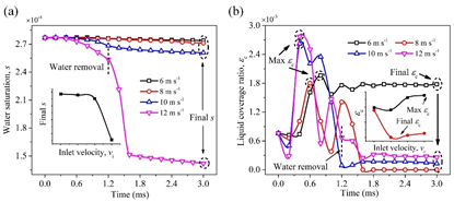
Fig. 6. Time variations of: (a) water saturation, (b) liquid coverage ratio in cases 3-6 with different inlet velocities.
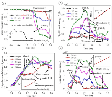
Fig. 7. Time variations of: (a) water retention ratio, (b) liquid kinetic energy, (c) liquid removal distance, (d) liquid coverage ratio in cases 5, 7-10 with different droplet sizes.
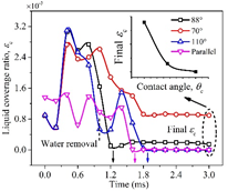
Fig. 8. Time variations of liquid coverage ratio in cases 5, 11-13 with different baffle contact angles and flow field designs.
Besides, we also carried out analysis on the equivalent force on the liquid droplet. Since the structure of 3-D flow field is complex, it is quite difficult to directly predict liquid behavior through force analysis. Based on the liquid removal distance and liquid kinetic energy (Figs. 7(a) and (b)), the equivalent force on droplet can be calculated in an indirect way. We found that the relationship between equivalent force and droplet size shows a similar rule to that of barrier-free channel. Therefore, as the droplet motion is still driven by air drag force and surface tension, it is possible to propose an empirical equation with geometric correction factor to describe two-phase behaviors of 3-D flow field.
In summary, it is found that the convective-and-uniform flow and liquid-gas separated transport both contribute to the mass transfer and water management of PEM fuel cells at high operating current density. While on the other hand, how the water accumulating on above-baffle area is expelled, how to treat the baffle surface to maintain expected water management and corrosion resistance characteristics and whether the manufacture cost of this fine structure can satisfy the requirement of wide commercialization, these kinds of problems still hinder the advancement of fuel cell technology. To figure out the unclear mechanism and technical obstacles of novel flow field/bipolar plate, there’re still numerous problems to be further investigated.
Z. Bao, Z. Niu, K. Jiao, Analysis of single- and two-phase flow characteristics of 3-D fine mesh flow field of proton exchange membrane fuel cells. J. Power Sources 438 (2019) 226995.